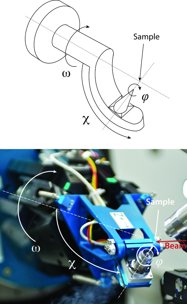
Figure 1.
The PRIGo goniometer as mounted at beamline X06DA (PXIII) at SLS. The sketch of an arc (top) and a photograph of PRIGo at beamline X06DA (PXIII) at SLS (bottom) are represented with the ω, χ and ϕ angles overlaid. The beamline coordinate system is as follows: the X axis is along the spindle or ω axis, the Y axis is oriented vertically upward, and the Z axis is along the beam direction.

