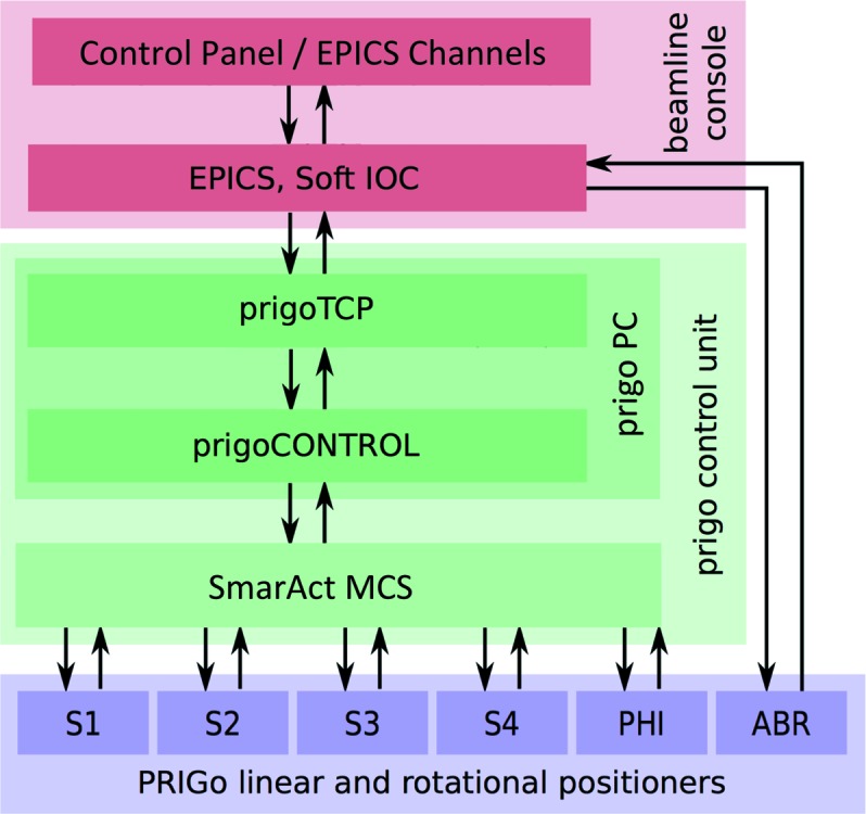
Figure 3.

PRIGo software. The schematic shows the different modules of PRIGo’s software and their interactions (represented by arrows). PRIGo’s control system receives commands from the input/output control servers (IOC) of the EPICS framework, which also controls the other beamline components including the air-bearing rotary stage (ABR). Within the PRIGo control unit, a transmission control protocol (TCP) server handles all communication (commands and feedback) over a TCP socket connection. The TCP server also receives the ABR ω position via EPICS, which is used by the PRIGo control to perform the active correction (see §3). The SmarAct positioners (S1–S4: SmarAct positioners, PHI: SmarAct rotary stage) feedback loop is controlled by the modular control system (MCS) from SmarAct GmbH.
