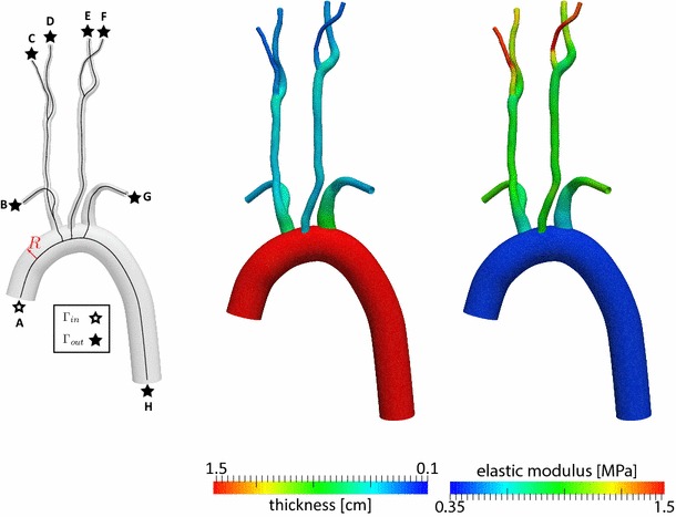
Fig. 2.

Left Model geometry with center lines and local radius ; center lines were calculated using the Vascular Modeling Toolkit http://www.vmtk.org/. Center Wall thickness, units in cm. Right Elastic wall modulus, units in MPa. Figure legend: A ascending aorta, B right subclavian, C right external carotid, D right internal carotid, E left internal carotid, F left external carotid , G left subclavian and H descending aorta
