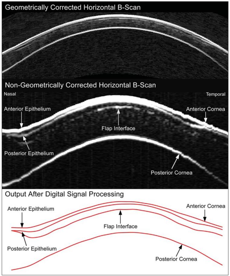
Figure 1.
Upper panel) Geometrically corrected horizontal B-scan image obtained using the Artemis very high-frequency (VHF) digital ultrasound arc-scanner. Middle panel) Non-geometrically corrected horizontal B-scan obtained using the Artemis VHF digital ultrasound arc-scanner. The image has been zoomed with different scales for the x and y axes; the width of the image corresponds to 10 mm whereas the height of the image corresponds to 1.2 mm. Lower panel) Digital signal processing is performed on the B-scan signal, and layer thickness measurements are obtained by a computer algorithm on the I-scan, resulting in the red line image of the interfaces.

