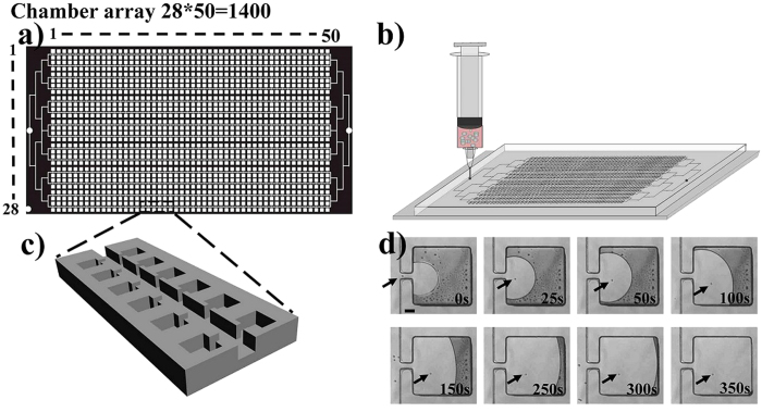
Figure 1. Schematic view of the device and cell suspension injection,
(a) the structure of the designed chip. (b) cell suspension injection into the chip. (c) enlarged view of the chamber array. (d) dynamic course of single cell self-loading into the lateral chamber. The arrows refer to a single cell. Scale bar in Fig. 1d is 100 μm.

