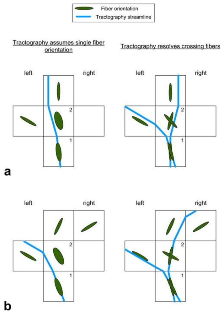
Figure 3.
Hypothetical examples (a and b) of tractography, which assumes single fiber orientation, i.e. DTI tractography (left column), and tractography, which resolves crossing fibers, i.e. DKI tractography (right column). Tractography that assumes single fiber orientation failed to show the leftward asymmetry (a) and falsely showed the leftward asymmetry (b). Voxels 1 and 2 are regions with crossing fibers. Streamlines were seeded in voxel 1 and propagated through the voxels according to the FACT algorithm (Mori et al., 1999; Xue et al., 1999). Tractography that assumes single fiber orientation started with one streamline (in blue), whereas tractography that resolves crossing fibers started with two streamlines.

