
Figure 1.
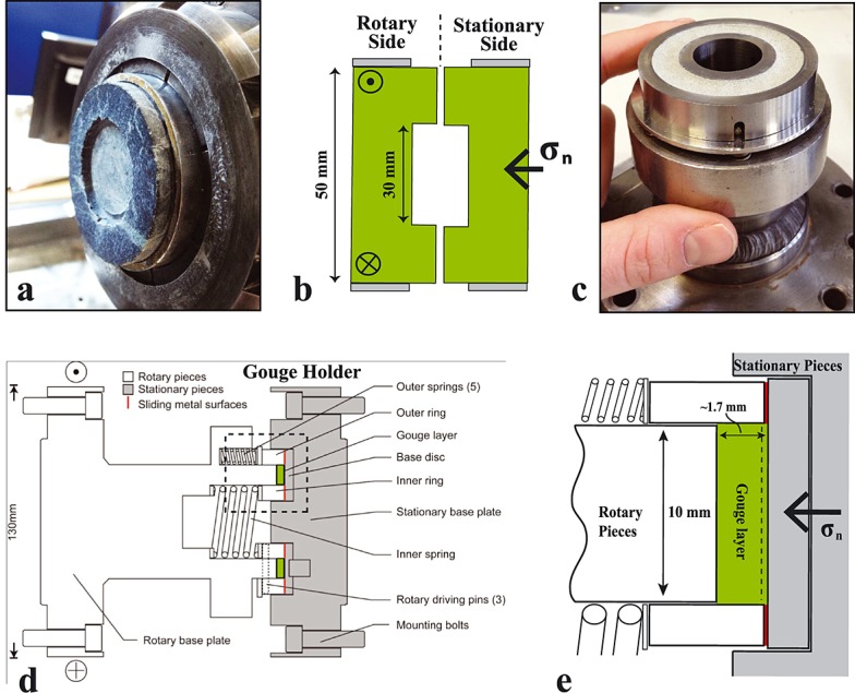
Sample assembly for bare surface and gouge experiments. (a) Photograph of rotary side of bare surface sample holder with serpentinite sample prior to deformation. (b) Schematic of bare surface experimental assembly. (c) Photograph of gouge holder (rotary side) loaded with serpentinite powder. (d) Schematic of gouge holder (modified after Smith et al. [2013b]). (e) Enlargement of Figure 1d showing gouge sample compartment (green) and lubricated metal-metal rotary contacts (red). Dashed line indicates typical location of strain localization within the gouge.