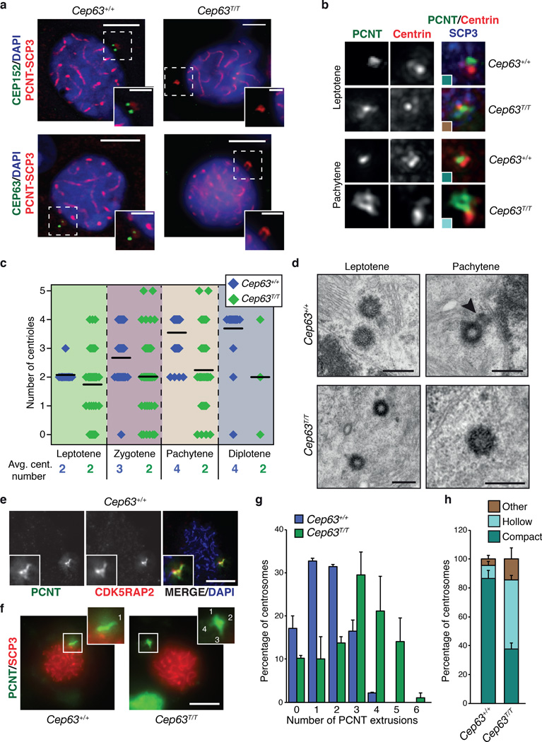
Figure 6. Centriole duplication failure during meiotic prophase I in Cep63T/T mice.
(a) CEP152 and CEP63 are detectable at centrosomes, marked by PCNT, in the SCP3 staged prophase I cells of WT (left panels) but not Cep63T/T (right panels) (scale bars represent 5 µm (left) and 2 µm (right)). (b) Example images of centriole configurations detected by immunofluorescence microscopy in spermatocytes at the indicated stage and of the indicated genotype. The colors of the insets correspond to the colors used for the graph in panel h. (c) Quantification of centriole numbers in prophase I spermatocytes at the indicated stage and of the indicated genotype. Example images are shown in panel b and in Supplementary Fig. 5. Average centriole number per stage is indicated (black line) and the value rounded to a whole number shown numerically below (3 animals per genotype used, Cep63+/+ n = 121, Cep63T/T n = 130 cells scored). (d) TEM analysis of centriole configurations in WT and Cep63T/T spermatocytes at the indicated stages. The arrowhead points to a daughter centriole growing from the wall of the mother (scale bar = 400 nm). (e) Co-distribution of the two PCM markers PCNT and CDK5RAP2 in squashes of WT spermatocytes. SCP3 staining was used for staging. (f) Examples of PCM extrusion patterns detected by PCNT staining in WT and Cep63T/T spermatocyte squashes. SCP3 staining was used for staging. The insets show magnifications of the PCM region, with extrusions labeled by numbers (scale bar = 5 µm). (g) Quantification of centrosome extrusions (PCNT staining) in spermatocytes of the indicated genotypes (n = 2 animals per genotype used, 92 Cep63+/+ and 87 Cep63T/T cells scored). (h) Quantification of PCM distribution (PCNT staining) patterns in spermatocytes from WT and Cep63T/Tmice (n = 3 animals per genotype used, 121 Cep63+/+ and 130 Cep63T/T cells scored). Additional PCM marker analysis is included in Supplementary Fig. 6. All graphs with error bars are presented as the average plus standard deviation.

