
Figure 3.
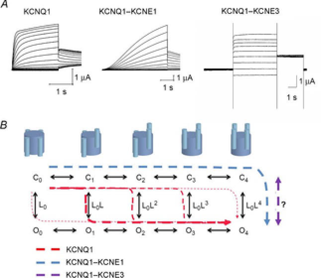
Model for KCNQ1 gating
A, representative K+ current families for KCNQ1 (stepping from a holding voltage of –80 mV to test voltages from –80 to +60 mV in 10 mV increments. Tail voltage is –30 mV), KCNQ1–KCNE1 (stepping from a holding voltage of –80 mV to test voltages from –110 to +60 mV in 10 mV increments. Tail voltage is –30 mV), and KCNQ1–KCNE3 (stepping from a holding voltage of –100 mV to test voltages from –100 to +60 mV in 20 mV increments. Tail voltage is –40 mV). B, ten-state model with five closed states (C0–C4) and five open states (O0–O4), where subscript depicts the number of activated S4s. Horizontal transitions are independent activation of S4s and vertical transition is the opening of the gate (with a potential extra concerted movement of all four S4s; Barro-Soria et al. 2014). Suggested transitions for KCNQ1 alone (red dashed lines), KCNQ1–KCNE1 (blue dashed line), and KCNQ1–KCNE3 (magenta dashed line) in response to a depolarization. Even at very negative voltages (all S4s down), KCNQ1 expressed alone displays a significant open probability that increases with more activated S4s (Osteen et al. 2012). In response to a depolarization, most KCNQ1 channels open after one or two S4s have activated (thicker red dashed lines). In contrast, KCNQ1–KCNE1 only opens after all four S4s have activated (all four S4s up; Barro-Soria et al. 2014), whereas in KCNQ1–KCNE3 the S4s are always activated independently of voltage and channel opening is relatively voltage independent (Nakajo & Kubo, 2007; Rocheleau & Kobertz, 2008).