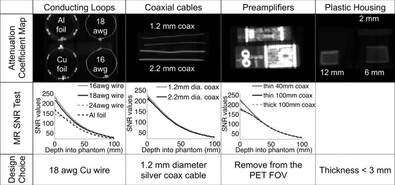
Figure 1.

511 keV attenuation map of coil components evaluated for the design of the 31-channel PET/MR array coil (1st row), showing high attenuation of the preamplifiers and thick metal or plastic components. Each electrical component was tested for its MR SNR in a single-loop configuration on a water phantom (2nd row). The final design choices reflect the goal to reduce attenuation but preserve SNR for MRI (3rd row).
