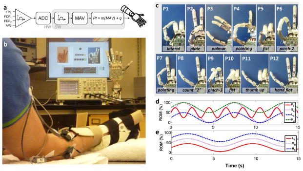
Fig. 1.

Experimental setup. (a) Block diagram of the myoelectric controller. FPL: flexor pollicis longus. FDP1, FDP2: first and second compartment of the flexor digitorum profundis. APL: abductor pollicis longus. ADC: analog to digital converter. MAV: mean absolute value. Pt: posture control command sent to the robotic hand. (b) Subject wearing an orthopedic splint on the experimental hand sat in front of a computer screen and the robotic hand. Computer screen presented desired posture cues while the hand was controlled in real-time. (c) Pictures of the 12 target postures P1..P12 used in experiment 1. Last two fingers of the hand are not shown for clarity (since these were not under direct control). It is worth noting that the target position of the fingers in postures P5 and P10 are similar but the two postures required activations with different timing in order to position the thumb properly (under the index and middle in posture P5; over the index and middle in P10). (d), (e) Representation of the sinusoids that subjects tracked in experiment 2A–B, respectively.
