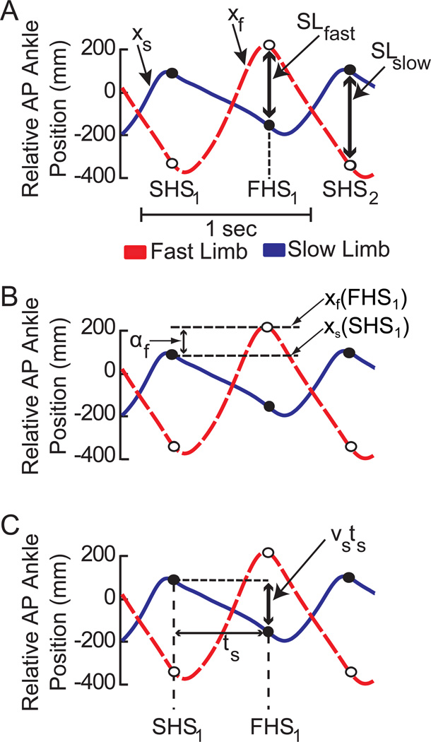
Figure 2.
Illustration of parameters used to derive the spatial and temporal contributions to step length. Each panel contains representative trajectories of anterior-posterior ankle position relative to the hip for the same subject during the early phase of split-belt adaptation. Positive values indicate that the ankle is in front of the hip. Dashed red traces represent the relative ankle position of the fast limb (xf) while solid blue traces represent the ankle position of the slow limb (xs). Open and closed circles represent the locations of the fast and slow markers respectively at heel strike of the leading limb. a) Representation of fast (SLfast) and slow (SLslow) step lengths. SHS1, FHS1, and SHS2 correspond to the initial slow heel strike, the subsequent fast heel strike, and the second slow heel strike respectively. b) Graphical representation of the spatial contribution to the fast step length (af). The spatial contribution is determined by the difference in the leading ankle positions on consecutive heel-strikes. Note that shifts in timing (x-axis) do no affect the amplitude of this component. c) The temporal contribution to step length is determined by the time between heel strikes (t) and the average velocity (v) of the trailing foot relative to the hips during the interval between heel strikes. Spatial shifts in the ankle trajectory (y-axis) do not affect the temporal contribution.

