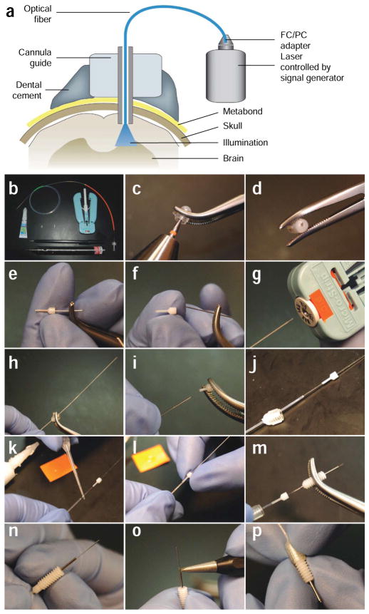
Figure 3.
Preparation of the optical fiber for in vivo neural control in mammals. (a) Diagram of the optical neural interface (ONI), consisting of a stereotactically implanted cannula, an optical fiber, and a solid state laser controlled by a signal generator. The fiber is prepared with the appropriate length to illuminate the target brain region. (b) The tools and parts (fiber with FC connection, dummy cannula, internal cannula, cannula guide, dental drill, super glue, diamond scribe and fiber stripping tool) needed to manufacture ONI fibers. (c,d) A drill is used to produce a small bore on the center of a cannula cap. (e,f) The steel tubing is removed from an internal cannula. The plastic adapter is used as the fiber guide. (g) A fiber stripping tool is used to remove the plastic cladding from a fiber to reveal the fiber core. (h) The bare fiber core is threaded through the bore on the cannula cap. (i,j) The plastic adapter from the internal cannula is also placed on the fiber. (k,l) Superglue is applied to the fiber to secure the plastic adapter against the plastic cladding on the fiber. The plastic adapter is held tightly against the fiber cladding for several minutes to allow the superglue to harden. (m) After superglue has hardened, the fiber is inserted through a cannula guide with the right projection length for the target brain region. (n) The cannula guide is securely clipped into the plastic adapter. (o) A diamond scribe is used to remove the excess fiber from the tip of the cannula guide. (p) The finished ONI fiber is allowed to protrude from the tip of the cannula guide by ~0.5 mm. Part a was modified with permission7 (Nature © 2007; Macmillan Publishers Ltd.).

