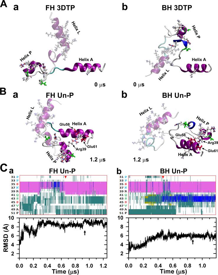
Fig. 2.
(A) Interacting heads motif (PDB 3DTP) free (a) and blocked (b) heads RLCs NTE peptides starting structures used for the MD simulations. The helices A of both myosin RLCs are at the right. Both unphosphorylated (un-P) compact peptides stabilized after ~1.2 νs in the two conformations shown in (B), remaining compact, with helix P inter-domain folded or bent close to helix A making a helix-coil-helix (HCH) motif. A network of salt bridges was established between R39 of helix P and residues E58 and E61 of helix A (Table 1). The evolution of the secondary structure of both NTE helices PPKC (Ser32-Arg38) and PMLCK (Ala40-Phe48) regions (cf. Fig. 1Cb) along each peptide trajectories is shown at top of (C): the α-helix content (pink) of helix PPKC sequence of the free head (a) does not change substantially after ~ 0.65 μs (red arrowhead) while the helix PMLCK is mostly turn (cyan) and coil (white). The blocked head helix content (b) increase by the presence of 3-10 helix (blue) after ~ 0.45 μs (red arrowhead), and the turn (cyan) and coil (white) content stabilizes. In both heads the root mean square deviation (RMSD) shows little changes after ~ 0.9 μs (C, bottom, black arrows). After stabilizing to the final snapshots shown in (B), the free and blocked head peptides were then phosphorylated at Ser35 (Fig. 5a) or Ser45 (Fig. 4a) respectively. Secondary structure colour key: 3-10 helix (blue), α-helix (pink), turn (cyan), coil (white), β-sheet (yellow). In this figure and in figures 4-6 the helix L is shadowed to emphasize the changes in the helix P conformation.

