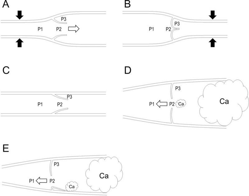
FIGURE 4.

Schematic illustrations of lymph flows and fluid pressures at various points in a lymphatic vessel. The labeled pressures are in front of the valve (P1), in the funnel-shaped space between valve faces (P2), and in the pocket (P3). White arrows indicate the flow direction. Black arrows indicate an intrinsic or extrinsic lymphatic pump force. Ca indicates cancer cells. A: If P1 > P2 > P3, the valve is open, and fluid flows in an anterograde direction. B: If P1 = P2 < P3, the valve is closed. C: If P1 = P2 = P3, the stoppage of fluid flow occurs. D: If P1 < P2 = P3, the valve is open, and fluid flows in a retrograde direction. This situation can arise if P3 increases due to the lymphatic invasion of cancer cells and the regurgitation of lymphatic valves occurs due to lymphatic ectasia even if this regurgitation is not continuous. E: If P1 < P2 = P3, the valve is open, and fluid flows in a retrograde direction. This situation can arise if P3 increases due to the lymphatic invasion of cancer cells and the regurgitation of lymphatic valves occurs due to the adhesion of cancer cells to the endothelium even if this regurgitation is not continuous.
