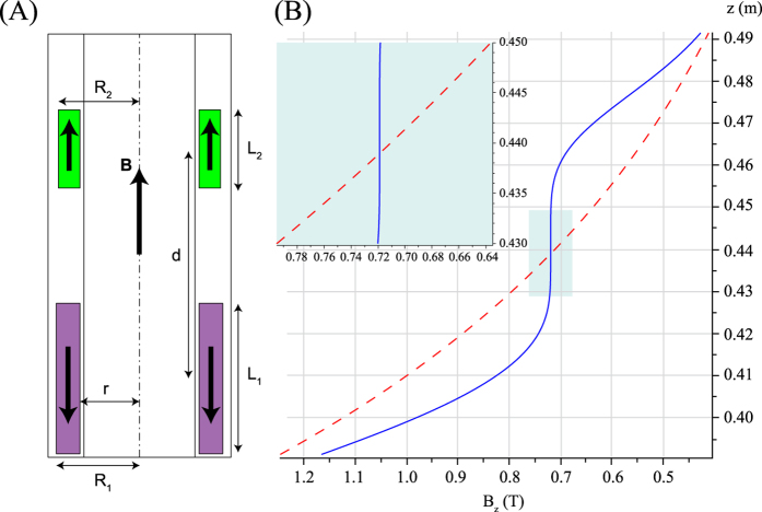
Figure 2.
(A) Schematic diagram of the bore of the superconducting magnet together with two axially magnetized, rectangular cross section permanent magnet rings. The magnet rings are depicted in green (resp. magenta) if the magnetization is parallel (resp. antiparallel) to the magnetic field of the superconducting magnet. (B) Magnetic field profiles without (red dashed curve) and with (blue plain curve) the compensation from the two rings. The red curve comes from the interpolation of measured data from an 11.7 T wide bore magnet, while the blue curve is calculated assuming perfectly uniform magnetization inside each ring. Here a third order compensation was realized to provide a much larger sweet spot as can be appreciated in the insert of (B). The z coordinate corresponds to the distance from the center of the superconducting magnet.

