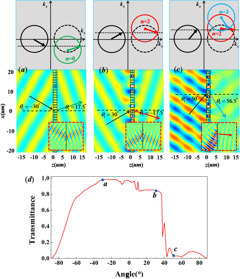
Figure 3. The case of metallic grating with ξ = 0.8k0.
(a–c) are simulated magnetic field patterns for incident wave with different angles with θi = −30°, 30° and 50° respectively. The upper parts are the corresponding iso-frequency contours, while the corresponding patterns of plane wave incident on metallic grating are placed in the nether parts, where the patterns for Gaussian beams bumping on the metallic grating with 6 supercells are inserted in bottom, which are marked by the red dashed frames. (d) is relationship between transmittance and incident angle. The points a, b and c in (d) denote the corresponding transmittance for the above cases of (a–c), respectively.

