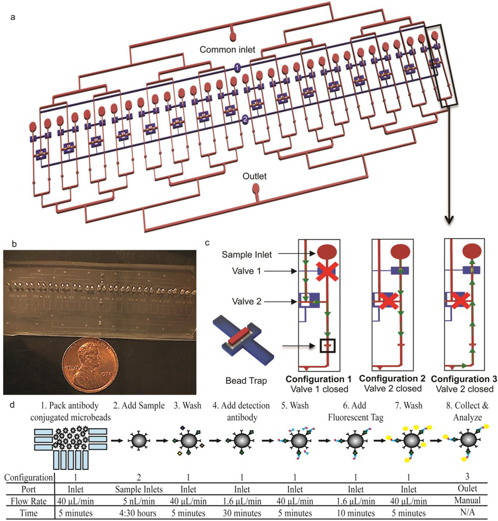
Fig. 1.
Device layout and assay principle a) Overall schematic of the device. The blue channels represent the pneumatic control layer and the red channels and gold valve seats denote the fluidic network b) Photograph of the device. The entire device measures 3 inches wide by 1 inch long, designed to fit on a standard glass slide c) Schematic of the valve states and fluidic paths through individual channels during different assay steps. The valves are actuated by pressurizing the inlets of the respective pneumatic channels, labeled 1 and 2 in Fig. 1a d) Overview of the assay workflow. The valve configuration and fluidic path (shown in panel c), port used for the introduction of the solution, flow rate, and duration is specified for each assay step

