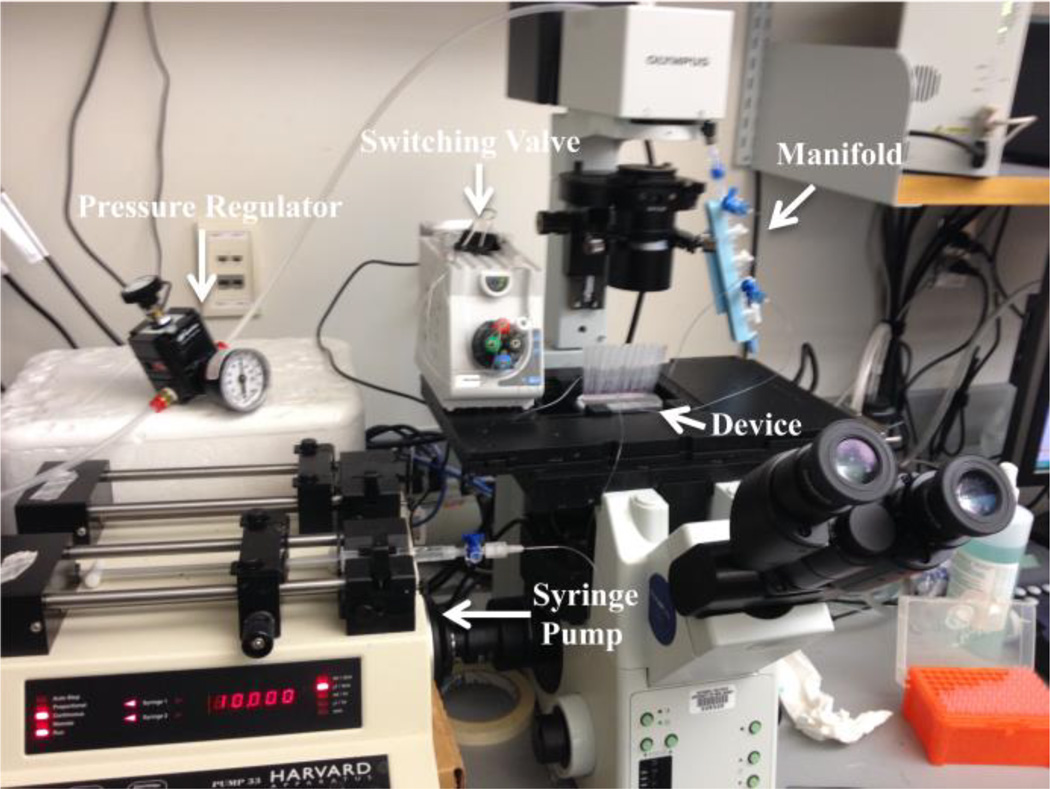
Fig 2.
Experimental system. The device is mounted on a microscope stage. The syringe pump is connected to a switching valve which is also connected to the device inlet for all assay steps in Configuration 1 (see Fig. 1c), facilitating the switching of solutions introduced into the device without removing tubing. In Configuration 2, the syringe pump is connected to the outlet of the device and set to withdraw fluid, pulling samples from the pipette tips inserted in the sample ports over the bead beds. In Configuration 3, the syringe is removed from the syringe pump and solution is manually infused through the outlet to collect the beads in pipette tips inserted into the sample ports. A pressure regulator provides compressed air to the manifold connected to each individual pneumatic channel allowing for each pneumatic valve to be individually opened and closed.

