Abstract
The auditory brainstem implant (ABI) restores hearing in patients with damaged auditory nerves. One of the main ideas to improve the efficacy of ABIs is to increase spatial specificity of stimulation, in order to minimize extra-auditory side-effects and to maximize the tonotopy of stimulation. This study reports on the development of a microfabricated conformable electrode array with small (100 μm diameter) electrode sites. The latter are coated with a conducting polymer, PEDOT:PSS, to offer high charge injection properties and to safely stimulate the auditory system with small stimulation sites. We report on the design and fabrication of the polymer implant, and characterize the coatings in physiological conditions in vitro and under mechanical deformation. We characterize the coating electrochemically and during bending tests. We present a proof of principle experiment where the auditory system is efficiently activated by the flexible polymeric interface in a rat model. These results demonstrate the potential of using conducting polymer coatings on small electrode sites for electrochemically safe and efficient stimulation of the central auditory system.
1 Introduction
Auditory brainstem implants (ABI) are an alternative hearing strategy for patients suffering from sensorineural hearing loss who cannot benefit from cochlear implants (CIs) because of a disconnection between the peripheral and central auditory systems. ABIs target the cochlear nucleus (CN), the first processing station of the central auditory system, located at the dorsolateral surface of the brainstem1. ABIs provide auditory sensations and help with lipreading for most patients. However, speech hearing performance is relatively poor compared to the high outcomes obtained in most patients with CIs; in spare cases, audiologic outcomes of ABI patients are excellent2. The modest efficacy of auditory brainstem stimulation may be due to spread of electric current leading to broad activation of neurons along the tonotopic axis of the CN and stimulation of extra-auditory neurons, causing side-effects. Based on this hypothesis, improving the spatial specificity of stimulation is a route for improving the ABI clinical outcomes.
Clinical ABIs consist of a rigid 0.6 mm thick pad hosting 15 to 21 platinum electrode sites with a diameter in the 550μm to 700μm range embedded in silicone elastomer. The array is surgically inserted at the surface of the CN. ABIs are often found too rigid to conform the curvilinear surface of the CN thereby preventing efficient transduction of the electrical stimulation in the CN. Recent advances in flexible bioelectronics provide alternative materials and designs for implantable neural interfaces. In this paper, we propose using flexible polymers to engineer and manufacture a conformal ABI. A compliant substrate may also decrease the mechanical mismatch between the implant and the tissue, and minimize chronic inflammation3,4. The proximity of the stimulation sites to the targeted neurons combined with limited implant encapsulation may also decrease stimulation current thresholds and improve its efficiency. Spatial specificity of stimulation may also be improved by modifying the geometry and arrangement of the stimulation sites, e.g. higher electrode density and smaller electrode diameter. A major limitation to reducing electrode area is the associated higher electrode impedance and lower safely injectable charge during electrical stimulation. This reduces the effective dynamic range of current levels between stimulation and damage thresholds. Many potential solutions have been proposed to improve the electrode-electrolyte interface by lowering the electrode impedance and increasing their charge injection capacity (CIC). This may be achieved by increasing the surface roughness of the electrode. The electrode effective surface area is larger that its geometrical surface area and the charge injection is more efficient.
Among these potential solutions, conducting polymers (mainly Polypyrrole, PPy, and poly(3,4-ethylenedioxythiophene), PEDOT) have gained substantial interest over the past ten years for recording and stimulation electrodes5. Although PPy properties have been extensively studied in the literature, PEDOT is generally preferred for biomedical applications because of its higher electrochemical stability.6 The surface of a PEDOT film is usually rough; its hybrid ionic-electronic charge transfer properties allow for very efficient charge transfer to the biological medium5,7. Moreover, PEDOT coatings under stimulation conditions show an excellent biocompatibility, with good neuronal adhesion and growth in vitro8 and in vivo9. In vivo PEDOT electropolymerization has also been demonstrated, with good electrical performance and no impairment of function10. Although some studies report on a limited stability of PEDOT under repeated pulsing in chronic conditions11, it appears as a good alternative to metal films in an acute application aiming at improving charge transduction properties of electrode sites. In this paper, we report on the characterization of PEDOT with doping agent PSS (polystyrene sulfonate) deposited above thin film platinum electrodes by galvanostatic electropolymerization from a solution of EDOT:PSS. Imaging and electrochemical characterization of PEDOT:PSS deposited with different charge deposition conditions are presented. The electrode array is embedded in a flexible polyimide film, and its reliability upon bending is assessed. In an acute setting, we recorded electrically evoked auditory brainstem responses (eABRs), a far-field response generated by the sequential activation of the auditory nuclei in the brainstem12, induced by electrical stimulation of the CN with the flexible electrode array. eABRs are a simple and non-invasive way to assess the activation of the auditory system. eABRs are also used clinically; in fact, during ABI implantation surgery, they are used to help position the implant at the surface of the CN2.
2 Methods
2.1 Fabrication
The electrode arrays were fabricated using standard microfabrication processes.13,14 A sacrificial layer of Ti(5 nm)/Al(50 nm) was first deposited by evaporation on a silicon wafer. A first layer of polyimide (PI2611, HD Microsystems GmbH, Germany) was then spin-coated and cured (soft bake, 5 min at 120©C followed by hard bake for 2 hours at 300©C in a N2 oven). The interconnects layer (Ti/Pt/Ti, 75/350/75 nm) was then sputtered after O2 plasma surface activation and patterned by photolithography and RIE (reactive ion etching). A second layer of PI was subsequently spin-coated and cured. A 500 nm SiO2 layer was next deposited and patterned to serve as an etch mask. Patterning of the SiO2 film defines both the electrode active sites and the implant external shape. The oxide and polyimide films were etched by RIE. For thin polyimide implants (5-10 μm thick), SiO2 masking was replaced by a thick photoresist coating. The electrode arrays were subsequently released from the wafer by anodic dissolution of the Al layer (1 V bias, in saturated NaCl solution).13
2.2 PEDOT:PSS preparation and electropolymerization
PEDOT:PSS was electropolymerized from a solution of EDOT (0.1%w/v) and PSS (0.2%w/v) (both purchased from Sigma Aldrich). Prior to electropolymerization, the electrodes were cleaned with UV/Ozone treatment for 30s. Electropoly merization was performed galvanostatically at 0.75 mA/cm2 with a platinum counterelectrode and Ag/AgCl reference electrode. PEDOT:PSS coatings were electropolymerized with different deposition charges (75-600 mC/cm2) by increasing the deposition time. After electropolymerization, the devices were rinsed in dH2O and air dried.
2.3 Electrochemical measurements
2.3.1 Electrochemical impedance spectroscopy
Electrochemical measurements were made in a 3-electrode setup with a potentiostat (Gamry Reference 600, Gamry Framework) with a large area platinum counterelectrode and an Ag/AgCl reference electrode. Measurements were performed at room temperature, in PBS (pH:7.4). Complex impedances were measured by electrochemical impedance spectroscopy (EIS), with an AC voltage of 5 mV RMS and no DC bias, between 100 Hz and 1 MHz.
2.3.2 Cyclic voltammetry
Cyclic voltammetry was performed by cycling the potential between the limits of water electrolysis (typically -0.6 to 0.8 V) at a speed of 50 mV/s. Cathodic charge storage capacity was calculated by integration of the cathodic current over one cycle of CV.
2.3.3 Voltage transients
Charge injection capacity (CIC) is defined as the maximum charge that can be injected without the potential of the interface going beyond the limits of the water window. It was measured for a particular pulse waveform and frequency by increasing the current level step by step and measuring the voltage transients. This transient is composed for each phase of several components. The initial quasi-instantaneous drop is called the ohmic drop and is due to the resistance of the circuit and solution. It was defined as the drop in potential occuring during the first 10μs of the pulse. The potential at the interface after subtraction of the ohmic drop was used to measure CIC, the maximum charge for which the negative and positive potentials remain within the electrochemically safe window15.
2.4 SEM
Samples were imaged under vacuum in a Zeiss Merlin scanning electron microscope (SEM) with an accelerating potential of 0.8 kV and a current of 15 pA. Working distance was 4.1 mm and magnification was 15,000x.
2.5 Thickness measurements
Thickness of the PEDOT:PSS coatings were measured by mechanical profilometry, with a DektakCT stylus surface profiler. A force of 3 mg was used.
2.6 Bending tests
To perform bending tests, the PEDOT coated devices were bent around rods of radius of curvature ranging from 2, 1.75, 1.5, 1.25 down to 1 mm. The complex impedance spectrum of the electrodes was measured before the test and immediately after, and so on until the smallest bending radius. The coatings were also inspected with an optical microscope to detect potential cracks or delamination.
2.7 In vivo evaluation
All experimental procedures were performed in accordance with the National Institute of Health guidelines for the care and use of laboratory animals as well as approved animal care and use protocols at the Massachusetts Eye & Ear Infirmary, Boston, MA. In vivo tests were performed on Sprague-Dawley rats (350-500 g). Animals were first anesthetized with Ketamine (100 mg/kg) and Xylazine (20 mg/kg), and an occipital craniotomy was performed. After cerebellar aspiration, the rat dorsal brainstem was exposed and the array was placed on the surface of the CN. Stimulation was induced with charge-balanced biphasic symmetric pulses, 0.2 ms/phase, at 23 pulses/s. eABRs were recorded by subtracting the signals obtained from two subcutaneous electrodes placed on the vertex and behind the ipsilateral pinna of the animal, with respect to a ground electrode on the back of the animal. The first 10 ms of this signal following each stimulation pulse was averaged over 512 stimulus presentations.
2.8 Statistical tests
Results are expressed as mean ± standard error of the mean. Statistical significance of data was determined by an analysis of variance (ANOVA), with a post-hoc Tukey-Kramer test performed with Matlab software (The Mathworks Inc., Natick, MA) . A p-value was determined and significance was indicated by a value lower than 0.05.
3 Results
3.1 PEDOT:PSS electrochemical study
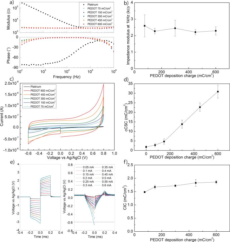
In the first phase of this study, we compared the electrochemical properties of the PEDOT:PSS coating at different deposition charges. Larger deposition charges generated thicker coatings (Fig. 1). The roughness of the coating surface is visible on the SEM image. PEDOT:PSS coating induced a decrease in impedance modulus at 1 kHz of more than one order of magnitude (from 45.27 ± 2.62 kΩ for Pt to 2.6 ± 0.66 kω for PEDOT:PSS of 0.6 μ±m thickness) (Fig. 2 a,b). Moreover, the phase of the impedance is close to zero over the entire range of measured frequencies, indicating a resistive behaviour associated with PEDOT:PSS charge-injection mechanism. The change of impedance between the different deposition conditions is not significant (p>0.05), indicating a negligible effect of the PEDOT:PSS thickness on the impedance modulus and phase.
Fig. 1.
a) Optical images of PEDOT films grown with various deposition charges (in mC/cm2). SEM image illustrating the surface roughness of the PEDOT:PSS coating. b) PEDOT:PSS film thickness as a function of deposition charge (N=5).
Fig. 2.
a) Electrochemical impedance spectra and b) impedance modulus at 1 kHz following PEDOT:PSS deposition with different deposition charges on 200 μm diameter electrodes (N=5). c) Cyclic voltammograms of 200 μm diameter PEDOT:PSS coated electrodes d) cCSC of PEDOT:PSS films prepared with increasing deposition charges (N=5). e) Voltage transients measured during biphasic current pulses and recorded with increasing stimulation currents, before (left) and after (right) removal of the ohmic drop on 100 μm diameter electrodes. (f) Average CIC of PEDOT at different deposition charges (N=5).
Cathodal charge storage capacity (cCSC) measurements obtained from the CV measurements show a non significant increase in cCSC between the platinum electrode and thinnest coating (p>0.05) (Fig. 2 c,d). Larger charge deposition generated a substantial and steady increase in cCSC (p<0.05 for all conditions).
Figure 2e displays an example of charge injection capacity measurement with a biphasic cathodic-first pulse at 20 Hz and 0.2 ms/phase. The voltage transients following current pulses of increasing amplitudes (0.05 to 0.6 mA) before and after subtraction of the ohmic drop are plotted. Figure 2f shows the behavior of the CIC of PEDOT:PSS-coated electrode sites with different deposition charges for 100 μm diameter electrode sites. A significant effect of the PEDOT:PSS deposition charge on CIC is obtained (p<0.05). A post-hoc test determined that only the 75 mC/cm2 is significantly different from other conditions (450 and 600 mC/cm2) (p<0.05).
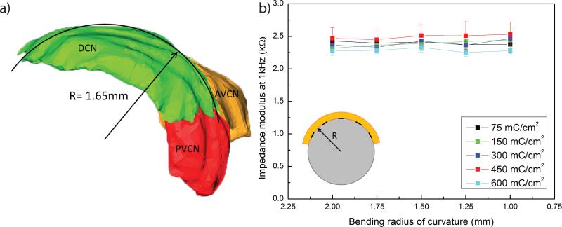
One important feature of the polyimide array is its flexibility. The PEDOT:PSS coating of the electrode sites must therefore remain intact upon bending to a radius of curvature corresponding to the estimated in vivo minimal bending radius, about 1.6 mm. This value was determined from a 3D reconstruction of a rat brainstem (Fig. 3a)16. Results of the bending tests show no significant change in impedance modulus at 1 kHz of the coated electrode sites, in all deposition charge conditions (p>0.05) (Fig. 3b). Furthermore, no cracks nor delamination of the coating were observed during any tested bending conditions.
Fig. 3.
a) 3D reconstruction of a rat cochelar nucleus. The dorsal cochlear nucleus has a radius of 1.65 mm16. DCN: dorsal cochlear nucleus, AVCN: anteroventral cochlear nucleus, PVCN: posteroventral cochlear nucleus. b) Impedance modulus at 1kHz of PEDOT:PSS coated electrodes (diameter = 200 μm) after increasing compressive bending.
3.2 Application and in vivo test
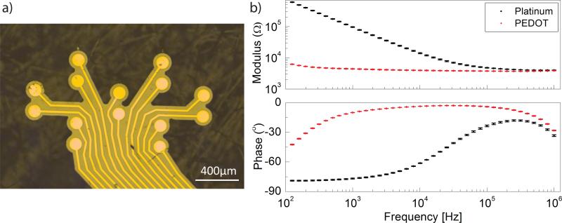
ABI arrays with a polyimide thickness of 8 μm were used for in vivo tests. With such thickness, the capillary forces are sufficient to induce a bending of the polyimide device around a wet cylindrical surface without any other external force applied17. A finger-like design was developed in order to further optimize the conformability of the array (Fig. 4a). In the context of this application, one desired feature is a high density of electrodes on the available 1-by-2 mm surface of the surgically exposed rat CN, in order to be able to precisely tune the stimulation position and optimize the spatial specificity of stimulation. An electrode diameter of 100 μm was selected for this purpose.
Fig. 4.
a) Picture of the electrode array fabricated on thin polyimide substrate with a finger-like shape to further increase conformability. b) Impedance modulus and phase spectra of a bare Pt and PEDOT:PSS coated electrodes (diameter = 100 μm). The small values of the error bars for the PEDOT:PSS coated electrodes (100 sites) demonstrate great repeatability of the coating.
Under these conditions, PEDOT:PSS with 75 mC/cm2 deposition charge was selected for further testing. Indeed, the low thickness of the polyimide substrate induces mechanically challenging conditions, and coatings with higher deposition charges tend to crack and delaminate from the substrate. The coating with 75 mC/cm2 deposition charge is the thinnest and thus has the least induced stress in the film.
Moreover, as mentioned in the previous section, the CIC and impedance values of the thinnest coating are very similar to the values at higher deposition charges. Choosing the thinnest coating thus guaranteed a greater mechanical stability without compromising the electrochemical properties and the safety of stimulation. A plot of the complex impedance spectrum of over 100 sites before and after coating with PEDOT:PSS at 75mC/cm2 shows repeatability of PEDOT:PSS coating impedance characteristics(Fig. 4b).
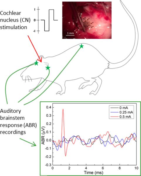
Another crucial property that we tested was the array's ability to generate eABRs. Results showed that it is possible to generate eABRs with the PEDOT:PSS coated electrode array. An example of electrically generated ABR is shown on Figure 5. Threshold for ABR generation is between 0.25 and 0.5 mA, and a large positive peak followed by a smaller negative peak can be seen, a waveform typical of electrically generated ABRs2.
Fig. 5.
Auditory brainstem responses (ABR) recorded following stimulation of the cochlear nucleus surface with the PEDOT:PSS coated electrode array. Photomicrograph shows the array in position on the exposed surface of the CN on the left side of the brainstem. Diagram shows the positions of the ABR recording electrodes.
4 Discussion
These results show the possible use of electropolymerized PEDOT:PSS coatings in a therapeutic application-driven study with acute in vivo tests. In a first phase, properties of PEDOT:PSS with different deposition charges were investigated. In a second phase, the application required thinner, more flexible polyimide substrate, which created a more mechanically challenging environment for the PEDOT:PSS coating. A 75 mC/cm2 deposition charge was hence selected, and proved to have electrical properties suitable for auditory brainstem stimulation. For this acute application, the PEDOT:PSS was very reliably electrodeposited and showed suitable properties in terms of size, thickness, bendability, impedance and charge injection capacity.
The electrochemical window limits are often considered to be between -0.6 and 0.8 V for platinum and −0.6 to 0.8 V or −0.9 to 0.5 V for PEDOT:PSS11,15. However, these limits highly depend on the conditions such as the temperature, the electrolyte composition and pH and the counterelectrode material. In order to measure them on a case-by case basis, CV cycles can be performed with very wide voltage limits. The negative voltage where the current drops and the positive voltage where the current quickly rises reflect water electrolysis and are the true limits of the water window. However, water window limits determined in vitro for this application will still be different from in vivo limits. The choice was then made to measure all electrochemical properties with respect to the −0.6 to 0.8 V limits. These values are quite conservative and widely used in the literature.
The stimulation used here is electrochemically safe in vitro at room temperature in PBS. However, the CIC can be very different in physiological conditions, at 37©C .15 Moreover, the electrochemical limit is not the only safety limit to consider for chronic stimulation. There is another limit of charge density above which the chronic overstimulation of neurons induces neuronal damage, first described by McCreery and coworkers.18,19 With 100 μm diameter electrodes and the pulse wave form used in this study, this limit corresponds to a current level of about 0.2 mA. This current is below eABR threshold during acute in vivo stimulation (about 0.5 mA). In order to develop a chronic stimulation model with this ABI array, the diameter would thus need to be increased. Moreover, the PEDOT:PSS coating electrodeposited on smooth platinum surface has been shown to be less stable than PEDOT:PSS or PEDOT:pTS (para-toluene sulfonate) electrodeposited on rough platinum for chronic applications11. This reduces delamination from the substrate and improves the electrochemical stability of the coating, which are currently the two main issues for developing a chronically stable coating with high charge injection capacity and small impedance. This is however beyond the scope of this paper, as the PEDOT:PSS coating is used here in an acute setup to help optimize stimulation parameters.
The particularity of the ABI application is its placement at the surface of the brainstem. Attempts have been made to develop a penetrating ABI (pABI) that is in closer proximity with the target neurons. Smaller currents were required to elicit auditory responses but overall, no significant improvements were observed compared to surface ABIs.20. Given the higher invasiveness of pABIs and the greater difficulty to adapt their placement during surgery, an optimization of the surface approach was chosen. The properties of this implant thus need to be halfway between intracortical electrodes and surface electrodes. The former have very small exposed areas and small current threshold due to close proximity to the target neurons but are usually associated to stronger chronic inflammation and high invasiveness, and the latter are less invasive and have larger electrode sites but have higher stimulation thresholds due to greater distance to target neurons. The challenge thus lies in the combination of minimally invasive, safe and efficient stimulation with small electrode sites and high spatial specificity. PEDOT:PSS was shown here to allow for the combination of safe and efficient stimulation with small electrode sites, therefore can be implemented to improve ABI functionality. Possible approaches to finely tune the stimulation characteristics include the adaptation of the stimulation waveform to the properties of the target neurons or current steering through careful selection of bipolar electrodes and inter-electrode distances. The use of PEDOT:PSS coating on small electrode sites thus provides a tool for the optimization of the ABI array and stimulation protocol, which might lead to a better understanding of the functionality of current clinical ABI arrays and eventually to an improvement of speech hearing outcomes.
Supplementary Material
Acknowledgements
This work was supported by the Fondation Bertarelli and the National Institute of Health (grant DC01089).
References
- 1.Vincent C. Hoboken NJ, editor. Anatomical record. 2012;295:1981–6. doi: 10.1002/ar.22588. 2007. [DOI] [PubMed] [Google Scholar]
- 2.Schwartz MS, Otto SR, Shannon RV, Hitselberger WE, Brackmann DE. Neurotherapeutics : the journal of the American Society for Experimental. NeuroTherapeutics. 2008;5:128–136. doi: 10.1016/j.nurt.2007.10.068. [DOI] [PMC free article] [PubMed] [Google Scholar]
- 3.Subbaroyan J, Martin DC, Kipke DR. J Neural Eng. 2005;2:103–113. doi: 10.1088/1741-2560/2/4/006. [DOI] [PubMed] [Google Scholar]
- 4.Nguyen JK, Park DJ, Skousen JL, Hess-Dunning AE, Tyler DJ, Rowan SJ, Weder C, Capadona JR. Journal of neural engineering. 2014;11:056014. doi: 10.1088/1741-2560/11/5/056014. [DOI] [PMC free article] [PubMed] [Google Scholar]
- 5.Asplund M, Nyberg T, Inganas O. Polymer Chemistry. 2010;1:1374–1391. [Google Scholar]
- 6.Cui XY, Martin DC. Sensors and Actuators B-Chemical. 2003;89:92–102. [Google Scholar]
- 7.Cui XT, Zhou DD. IEEE Trans Neural Syst Rehabil Eng. 2007;15:502–508. doi: 10.1109/TNSRE.2007.909811. [DOI] [PubMed] [Google Scholar]
- 8.Richardson-Burns SM, Hendricks JL, Foster B, Povlich LK, Kim D-H, Martin DC. Biomaterials. 2007;28:1539–52. doi: 10.1016/j.biomaterials.2006.11.026. [DOI] [PMC free article] [PubMed] [Google Scholar]
- 9.Ludwig KA, Uram JD, Yang JY, Martin DC, Kipke DR. Journal of Neural Engineering. 2006;3:59–70. doi: 10.1088/1741-2560/3/1/007. [DOI] [PubMed] [Google Scholar]
- 10.Ouyang L, Shaw CL, Kuo C-C, Griffin AL, Martin DC. Journal of neural engineering. 2014;11:026005. doi: 10.1088/1741-2560/11/2/026005. [DOI] [PMC free article] [PubMed] [Google Scholar]
- 11.Green RA, Matteucci PB, Hassarati RT, Giraud B, Dodds CW, Chen S, Byrnes-Preston PJ, Suaning GJ, Poole-Warren LA, Lovell NH. J Neural Eng. 2013;10:16009. doi: 10.1088/1741-2560/10/1/016009. [DOI] [PubMed] [Google Scholar]
- 12.Shaw NA. 1988:31. year. [Google Scholar]
- 13.Mercanzini A, Cheung K, Buhl DL, Boers M, Maillard A, Colin P, Bensadoun JC, Bertsch A, Renaud P. Sensors and Actuators a-Physical. 2008;143:90–96. [Google Scholar]
- 14.Rousche PJ, Pellinen DS, Pivin DP, Williams JC, Vetter RJ, Kipke DR. Ieee Transactions on Biomedical Engineering. 2001;48:361–371. doi: 10.1109/10.914800. [DOI] [PubMed] [Google Scholar]
- 15.Cogan SF, Troyk PR, Ehrlich J, Plante TD, Detlefsen DE. Ieee Transactions on Biomedical Engineering. 2006;53:327–332. doi: 10.1109/TBME.2005.862572. [DOI] [PubMed] [Google Scholar]
- 16.Verma RU, Guex A. a., Hancock KE, Durakovic N, McKay CM, Slama MCC, Brown MC, Lee DJ. Hearing research. 2014;310:69–75. doi: 10.1016/j.heares.2014.01.008. [DOI] [PMC free article] [PubMed] [Google Scholar]
- 17.Kim DH, Viventi J, Amsden JJ, Xiao JL, Vigeland L, Kim YS, Blanco JA, Panilaitis B, Frechette ES, Contreras D, Kaplan DL, Omenetto FG, Huang YG, Hwang KC, Zakin MR, Litt B, Rogers JA. Nature Materials. 2010;9:511–517. doi: 10.1038/nmat2745. [DOI] [PMC free article] [PubMed] [Google Scholar]
- 18.Merrill DR, Bikson M, Jefferys JGR. Journal of Neuroscience Methods. 2005;141:171–198. doi: 10.1016/j.jneumeth.2004.10.020. [DOI] [PubMed] [Google Scholar]
- 19.Mccreery DB, Agnew WF, Yuen TGH, Bullara L. Ieee Transactions on Biomedical Engineering. 1990;37:996–1001. doi: 10.1109/10.102812. [DOI] [PubMed] [Google Scholar]
- 20.Otto SR, Shannon RV, Wilkinson EP, Hitselberger WE, Mccreery DB, Moore JK, Brackmann DE. 2008:1147–1154. doi: 10.1097/MAO.0b013e31818becb4. [DOI] [PubMed] [Google Scholar]
Associated Data
This section collects any data citations, data availability statements, or supplementary materials included in this article.


