
Figure 3.
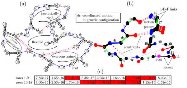
Example structure with protein backbone inspired geometry. (a) Body-bar graph representation. Double-headed (two single-headed) arrows indicate a five (six) bar connection with small accompanying numbers representing bars that are occupied with pebbles of the adjacent body. Free pebbles are shown as large numbers within the circular bodies. Apart from the six trivial rigid body motions collected at the root, we find one more free pebble that represents a floppy mode shared between star-tagged connections. (b) Tree representation of the structure, with dots as atoms and thick (thin, numbered) lines as locked (rotatable) bonds. Four dotted constraints partly rigidify the structure. The same dihedral angles are identified as flexible, producing the indicated motion pattern upon sampling of other configurations. Numbers correspond to associated rows in the nullspace matrix. (c) Nullspace matrix with one column and 18 rows obtained with our analysis. The red colored entries indicate the moveable, star-tagged dihedral angles, while vanishingly small entries belong to rigidified links. The matrix is an explicit basis for the resulting motion in (b).