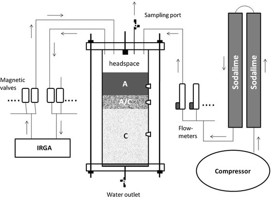
Fig. 2.

Schematic drawing of the incubation system (arrows indicate the direction of air-flow). Ambient air was compressed and pumped through sodalime-columns to scrub ambient CO2. Flow rates to the soil column headspace were regulated in a way that headspace CO2 concentrations ranged between 380 and 400 ppm. The flushing-air left the soil column headspace through an outlet which was also used as sampling port for isotopic analyses. Two benches of magnetic valves (inlet, outlet) allowed to switch between individual soil columns (n = 15) for CO2 concentration measurements with an IRGA. Water was added through a spray valve at the top of the column headspace and leaching water was collected from an outlet at the bottom of the soil column. At each soil horizon, a septum was installed into the column wall to allow direct sampling of soil–air with a syringe
