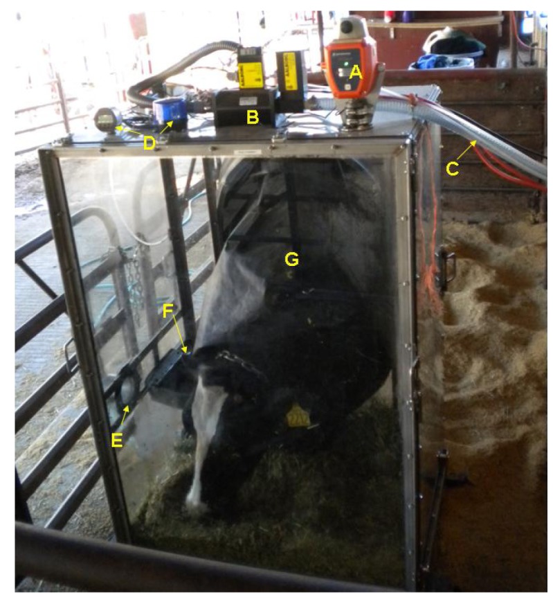
Figure 4.

A dairy cow standing and eating during a gas sampling period. (A) is the oxygen sensor/alarm; (B) is the mass flow controller; (C) is the main air line that was connected to the rotary vane vacuum pump; (D) is the differential pressure gage/alarm system; (E) is the air inlet opening; (F) is the water bowl for the cow; (G) is the neck sleeve.
