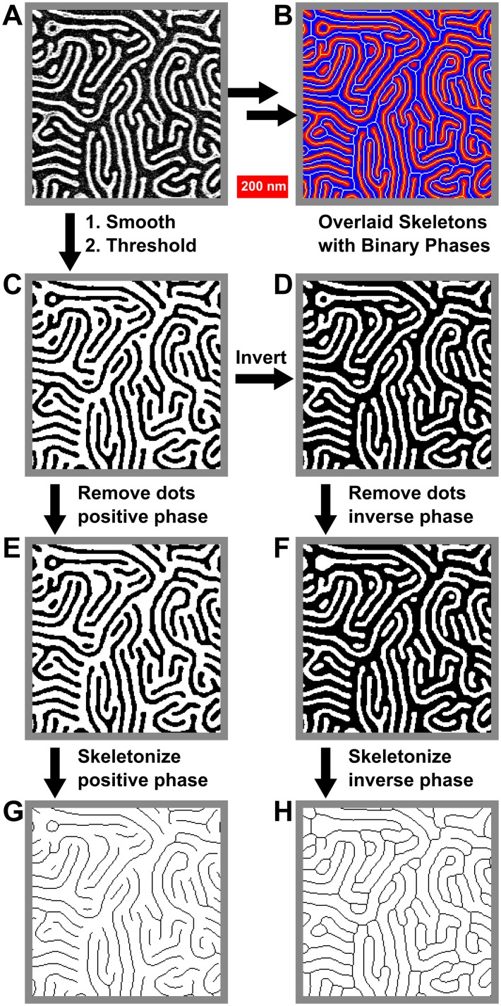
Fig 4. Process for the skeletonization of both positive and negative phases of a binary image.
(A) Original image. (B) Overlay of binary and skeletonised images showing retained connectivity. (C) Binary image. (D) Inverted binary image. (E) and (F) Processed images (C) and (D), with dots in respective phases removed. (G) and (H) Skeleton images derived from (E) and (F). Images are all 735 nm × 735 nm.

