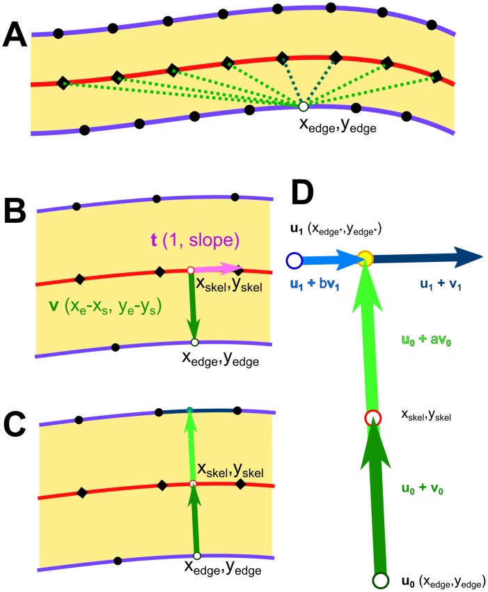
Fig 10. Diagram showing relationship between line edge points, skeleton points, and the vectors used to determine edge positions and line-widths for LER and LWR.
(A) Outline of a line, showing edge points (black dots) and skeleton points (black diamonds) on the centre line. One edge point (xedge,yedge) is selected and distances to nearest skeleton points are checked. (B) Interpolation to nearest orthogonal point from the edge point to a point on the skeleton segment. (C) Extension of edge-to-skeleton vector to intersection with transverse edge segment. (D) Expanded, with parameterization as scalable, intersecting vectors.

