
Figure 2.
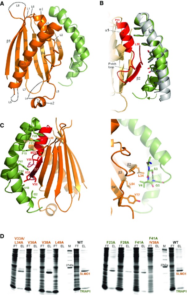
Crystal structure of the apo TRIAP1-SLMO1 complex
- Cartoon representation for the crystal structure of the TRIAP1-SLMO1 complex. TRIAP1 is shown in green and SLMO1 in orange with annotated secondary structure elements.
- Highlighted TRIAP1-SLMO1 interface with a superimposition of free TRIAP1 (grey) and bound TRIAP1 (green). The hydrophobic side chains of TRIAP1 are in green sticks, and the complementary interaction region on SLMO1 is shown as red cartoon. The rest of SLMO1 is shown as an orange cartoon.
- Hydrophobic interaction at the TRIAP1-SLMO1 interface. Left: cartoon representation of the TRIAP1-SLMO1 complex with key interfacial hydrophobic side chains shown as sticks and labelled with residue numbers. TRIAP1 is coloured green, and the complementary interaction region on SLMO1 is shown as red cartoon with the remaining sequence of SLMO1 shown as an orange cartoon. Right: hydrophobic contacts to the N-terminal V4 from TRIAP1.
- SDS–PAGE analysis of His-tag pull-down assays with His-SLMO1 and TRIAP1. For each sample, the column flow through (FT) and elution (EL) fraction are shown. SLMO1 mutants are shown in the left panel, and the lack of recovery of mutant complexes V36A and L49A suggests that these alterations disrupt the formation of the complex. TRIAP1 mutants are shown on the right, and while mutant complex can be purified for the single mutants, the complex is lost when F41A in TRIAP1 is accompanied by V38A in SLMO1.