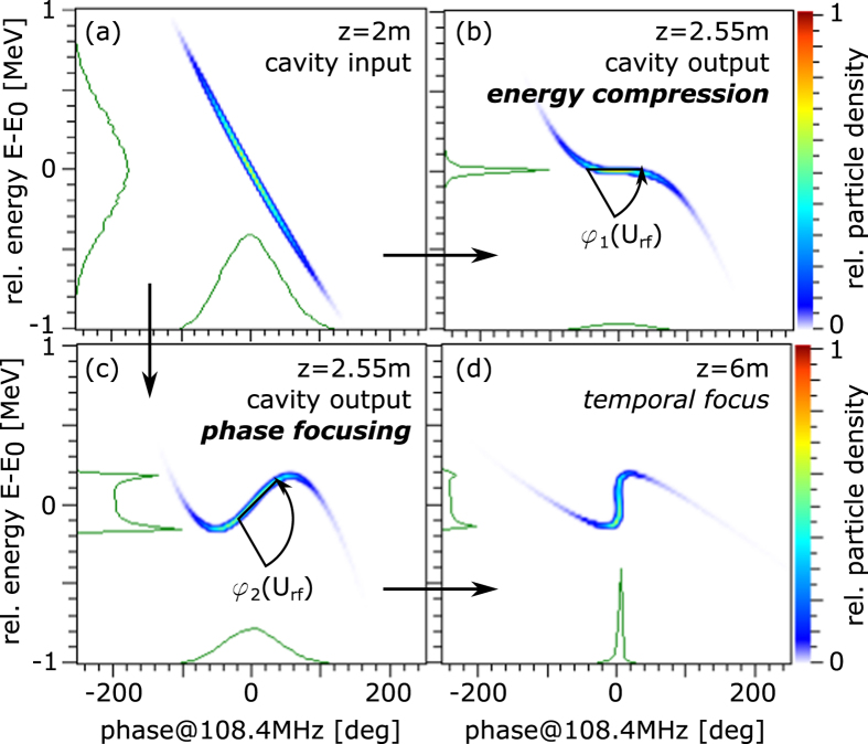
Figure 2. Illustration of phase rotation in longitudinal phase space via applied rf.
The input beam is shown for reference in (a) and the two operational modes of interest are depicted in (b) and (c): At an injection phase of ΦS = −90 deg the bunch is rotated around the central energy by an angle φ in dependency on the rf amplitude Urf. (b) represents the energy compression mode, see25 and (c) the phase focusing mode, which is described in this paper and leads to (d) a focus of the bunch in the time domain after a certain drift length.

