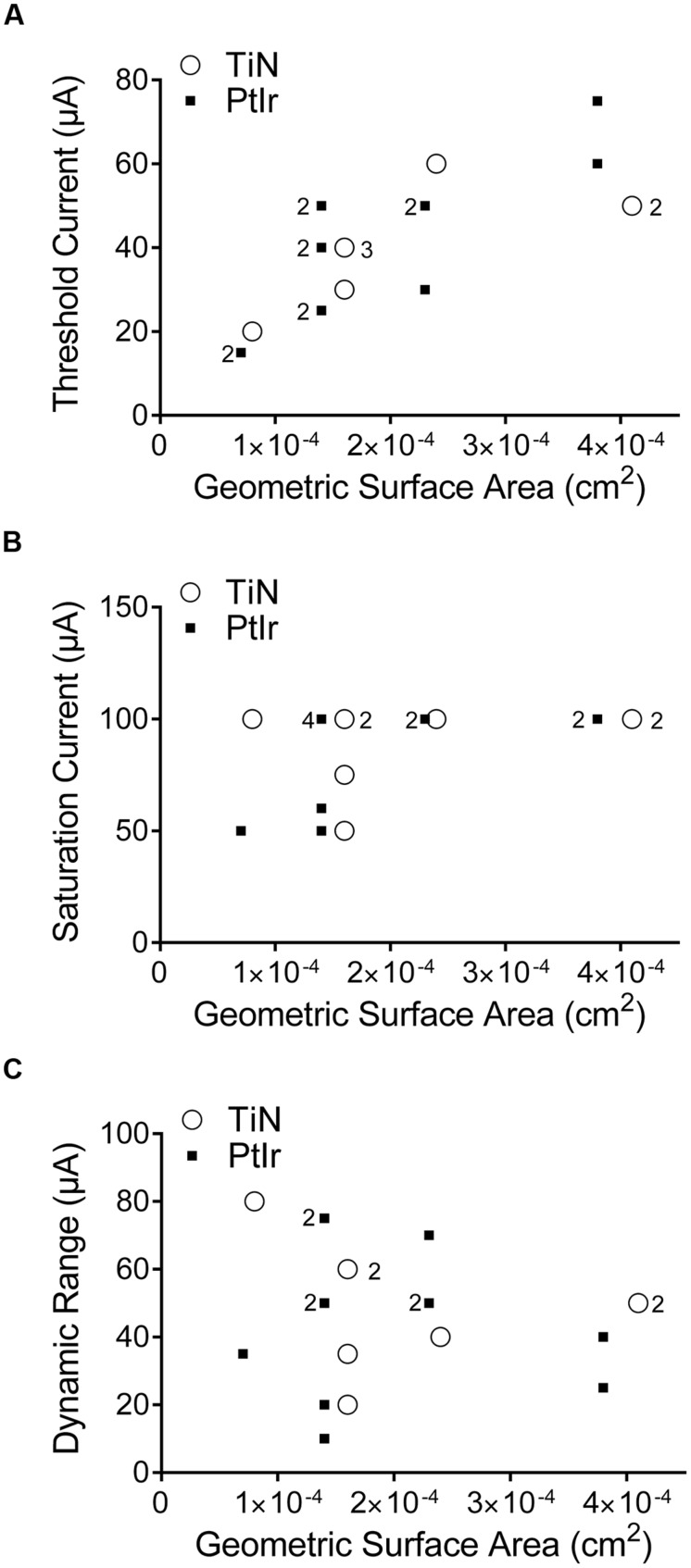
FIGURE 8.
Stimulation currents used versus the geometric surface area of the electrode. (A) Threshold current, (B) saturation current, and (C) dynamic range. TiN coated electrodes are indicated by open circles and uncoated PtIr electrodes are indicated by solid squares. The numbers to the left of a marker indicates the corresponding number of PtIr overlapping data points, the numbers to the right of a marker indicates the corresponding number of TiN overlapping data points. No number indicates only one electrode.

