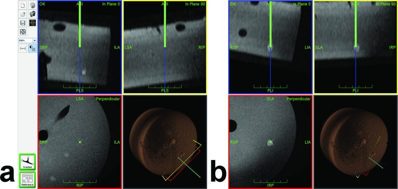
Fig 3. Navigation Interface During Target Approach.
The navigation interface continuously displays three orthogonal planes reconstructed from the planning MRI dataset along (in-plane 0° and in-plane 90°, blue and yellow frames) and perpendicular (red frame) to the tracked needle. The virtual needle and its extension are displayed as green and blue lines, respectively (virtual tip at the end of the green line). The fourth view indicates the 3D position of the needle and all viewing planes with respect to the volume-rendered MRI dataset. Phantom vessels (tubes) and targets (peas) appear as hypointense and hyperintense structures, respectively. (a) Sample screenshot of a partially inserted needle with the virtual extension slightly off target (#10, in plane 0°). Two other targets (#6 and #7) happen to appear in the perpendicular view. (b) Later screenshot after corresponding adjustment showing the virtual needle tip inside the target (in all views).

