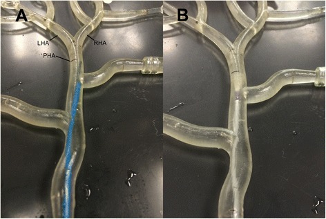
Fig. 3.

Catheter positions during fluorescent microsphere administrations. Photographs of the catheter positions in the geometry of the recreated hepatic arterial model, corresponding to the fluorescent microsphere administrations in Fig. 4. a Note the SMC tip deviation towards the right side. b Fixed centro-luminal position of the ARC. Abbreviations: LHA = left hepatic artery; RHA = right hepatic artery; PHA = proper hepatic artery. NB: the model is oriented up-side down
