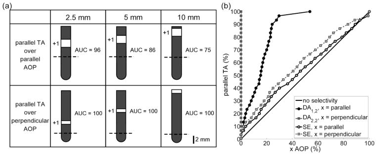
Figure 6.

Optimal electrode configurations for selectively activating terminating axons (TAs) over axons of passage (AOPs). (a) Optimal electrode configurations and corresponding normalized area under the curve (AUC, see Equation 4) when stimulating parallel TAs over parallel AOPs (row 1) and parallel TAs over perpendicular AOPs (row 2) when neural elements were placed ≤ 2.5 mm (column 1), 5 mm (column 2), and 10 mm (column 3) from the origin. The dashed line denotes z = 0. (b) The percentage of parallel TAs versus selected percentages of parallel or perpendicular AOPs for the distal anodes in row 1, column 2 (DA1,2) and row 2, column 2 (DA2,2) in part a. For comparison, the standard electrode (SE) in an anodic configuration was used to stimulate parallel TAs over AOPs.
