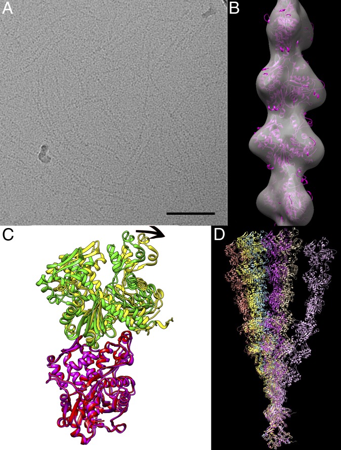
Fig. 1.
Crenactin filaments imaged by cryo-EM and crystallography. (A) A field of frozen-hydrated filaments over a hole in a lacey carbon grid. (Scale bar, 1,000 Å.) (B) The surface of a reconstruction is shown in transparent gray, and a crystal structure (magenta) of the crenactin subunit has been placed in the filament by rigid-body fitting. (C) The variability in filament-like subunit–subunit interfaces in crenactin crystal structures can be seen in this comparison between 4BQL chains D (magenta) and A (yellow) and chains C (red) and B (green) from the same crystal unit cell. Subunit C has been aligned to subunit D (0.8 Å rmsd), and the resulting transformation imposed on subunit B. The arrow at the top shows the considerable rotation between the two. (D) Six different filaments can be generated by imposing the six different interfaces in the two crenactin crystals. For example, the symmetry operation best relating chain A to chain B is found and then repeatedly applied to chain A to generate one filament, whereas a different filament will be generated by finding the symmetry operation relating chain B to the chain A above it. The filaments, from left to right (at the top) are 4CJ7_AB, 4BQL_BDs, 4BQL_AD, 4CJ7_ABs, 4BQL_ACs, and 4BQL_BC.

