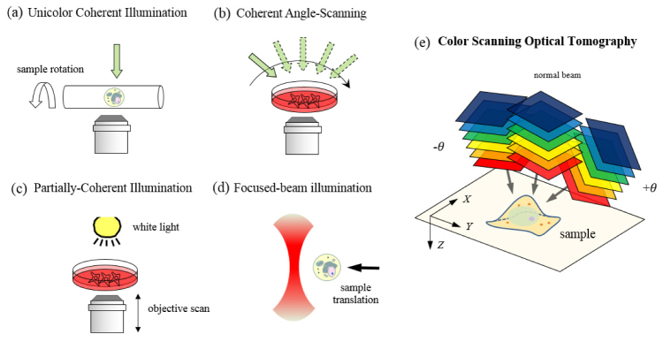
Fig. 1.

Tomographic optical microscopy in various configurations for three-dimensional refractive index mapping of a specimen: (a) Rotating-sample geometry [13]. (b) Rotating-beam geometry [5,14,15]. (c) Objective-lens-scan geometry [18–21]. (d) Scanning-sample geometry [22,23], and (e) color-scan geometry proposed in this study. The figure (e) also shows the spatial (X,Y,Z) coordinates used for derivation of the formula.
