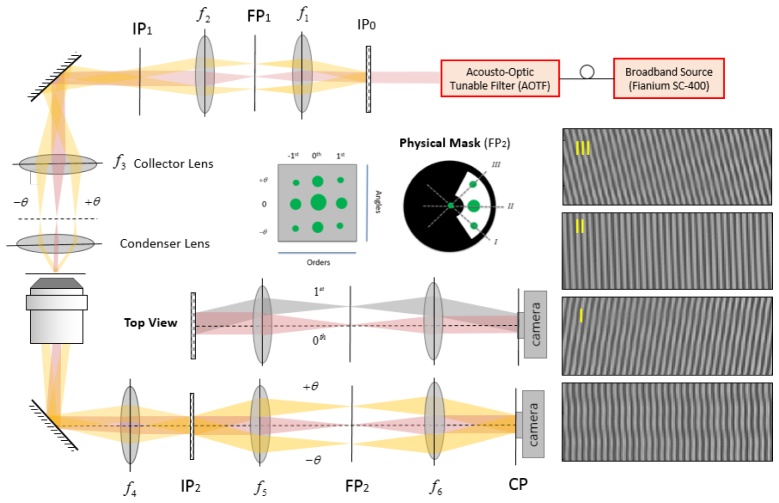
Fig. 3.
Schematic diagram of the experimental setup: SP (Sample plane); IP (Image plane); FP (Fourier Plane); Condenser lens (Olympus 60 X, NA = 0.8), Objective lens (Nikon 60 X, NA = 1.2). f1 = 30 mm, f2 = 50 mm, f3 = 200 mm, f4 = 200 mm, f5 = 100 mm, and f6 = 300 mm. Non-diffracted order is shown in red while yellow refers to the oblique illumination. Interferograms I, II, and III are decomposition of the raw interferogram (bottom right) into its three components. The physical mask placed at FP2, creates a reference by spatially cleaning the non-diffracted order while passing the 1st order sample beams that correspond to the three incident angles.

