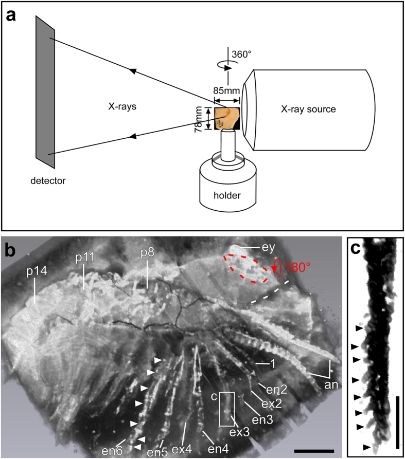
Figure 2. Micro-CT set-up and fine details revealed on the surface of the slab.
(a) The slab was placed as close to the X-ray source as possible to obtain the highest possible resolution in the final micro-CT images. The slab was rotated 360° during the process of scan, with a rotation radius of 42.5 mm. In this study, the anterior (Figs 2b and 3) and posterior (Fig. 4) parts of the specimen were scanned separately. (b) Fine details in the anterior part of the specimen revealed with micro-CT (volume rendering, Amira). Annulation of the antennae (an) is evident. The first post-antennal appendage (1) is uniramous and appears annulated. Exopod (ex) and endopod (en) of the 2nd to 4th post-antennal appendages are now clearly displayed. Elongated podomeres (white arrowheads) in the endopod of the 5th and 6th post-antennal appendages are shown. The blue dashed line marks a small region of the head shield, which was preserved in a flipped-over manner (blue arrow). The white dashed line indicates that the two parts of the head shield were torn apart from each other. (c) Close-up (Hires mode in Drishti) of the exopod shows a series of setae (arrowheads) at the distal end of the 3rd post-antennal appendage. Each seta is around 100 μm in length. Abbreviations as in Fig. 1. Scale bars, 2 mm in b, 1 mm in c. Photographs in a, b taken by G.S., in c by Y.L.

