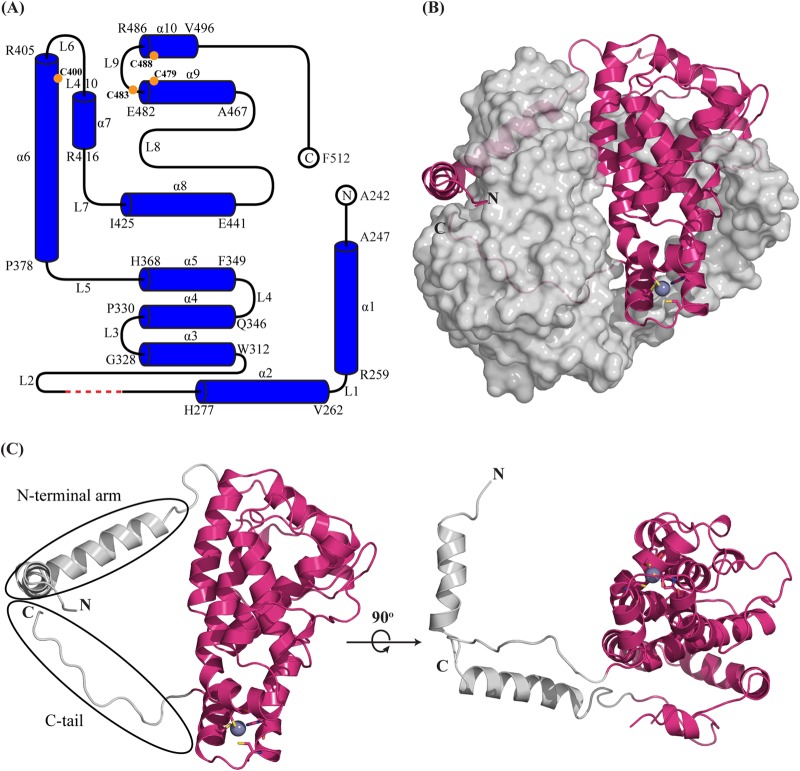
FIG 2.
Overall structure of ICP27-CTD. (A) A schematic representation shows that the ICP27-CTD monomer consists of 10 α-helices (α1 to α10), separated by nine loops (L1 to L9) of varied lengths. The model starts at A242 and ends at F512 with the residues from 190 to 241 and His6-TEV tag missing. The first and last residues of each helix are indicated. The red dashed line indicates the four residues (G298 to G301) with missing electron densities. The orange circles indicate the positions of the zinc-binding residues. The schematic was prepared using TopDraw software in the CCP4 suite. (B) Diagram representation of ICP27-CTD monomer (magenta) in close contact with the second monomer, shown as a gray surface representation. The N-terminal arm of the first monomer is wrapped around the second monomer, whereas the C-terminal region is buried. The zinc ion is represented as a purple-gray sphere and is tetrahedrally coordinated by cysteine and histidine residues shown as sticks. (C) Diagram representation of ICP27-CTD monomer shown in two views rotated 90° along the x axis. The helical core is magenta, and the N and C termini are gray. The rotated figure shows the hollow region between the globular domain and the N-terminal arm.

