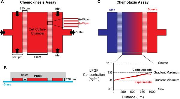
Fig. 2.
A microfluidic device for chemokinesis and chemotaxis assays. (A) The microfluidic device viewed from the top-down. The outermost channels (500 μm wide) are separated from the cell-culture chamber (CCC, 1 mm wide) by a micro-capillary array with capillaries (250 μm long and 10 μm wide) spaced 15 μm apart. For chemokinesis assays, the same medium is perfused into both outer channels to create a uniform concentration across the device and replenish growth factors. (B) A cross-sectional view of the microfluidic device. The medium-carrying channels and the CCC are 120 μm high. The difference in height between CCC and the micro-capillaries (10 μm) increases fluidic resistance and, consequently, minimizes flow within the CCC. (C) For chemotaxis assays, the outermost channels (“source” and “sink”) are perfused with media containing different bFGF concentrations to create a stable, linear concentration gradient. Computational transport models (black line) of the predicted concentration profile were validated with experimental studies (red line).

