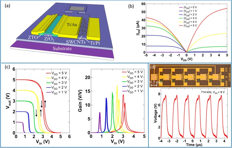
Fig. 16.

Heterogeneous integration of CNT (p-type) and ZTO (n-type) semiconductors for printed complementary integrated circuits. a Schematic diagram of the CMOS inverter. b Output characteristics of the printed n-type and p-type TFT. c VTC (left) and voltage gain (right) of the printed inverter under various supply voltages. d Printed 5-stage ring oscillator using the complementary inverters. Top: optical micrograph. Bottom: output signal of the oscillator driven by a V dd of 8 V. Reproduced from ref. [94]
