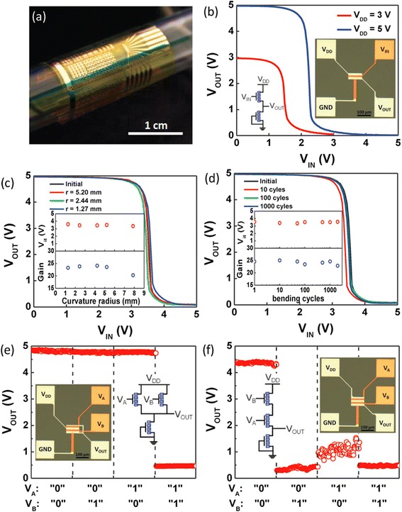
Fig. 3.

Flexible logic gates using CNT-TFTs. a Optical image demonstrating the flexibility of the circuits, where the sample is wrapped onto a glass tube with a diameter of 10 mm. b Inverter voltage transfer characteristics (VTC) measured with a VDD of 3 or 5 V. Inset shows the schematic and the optical picture of the diode-loaded inverter. c Inverter VTC measured while the circuit is bent to various curvature radii. Inset shows the inverter threshold voltage and gain as a function of curvature radius. d Inverter durability under cyclic bending test, showing stable performance for up to 2000 cycles. e, f Output characteristics of diode-loaded 2-input NOR (e) and NAND (f) gates. V DD is 5 V for both circuits. Insets are the corresponding schematic and optical micrographs. Reproduced from ref. [26]
