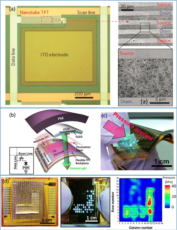
Fig. 5.

User-interactive electronic skin (E-skin) using CNT-TFTs. a Left panel: optical micrograph of one pixel before integrating OLED and pressure sensitive rubber (PSR). Right panel: SEM image showing the channel region of the CNT-TFTs. b Schematic diagram showing the exploded view of one pixel, consisting of a CNT-TFT, an OLED, and a layer of PSR vertically integrated on a polyimide substrate. c Operation of the E-skin system with 16 × 16 pixels, showing the OLEDs are turned locally on where pressure is applied. d Optical and electrical readout from the E-skin system when an L-shaped PDMS slab is used to apply pressure onto the sample. Reproduced from ref. [72]
