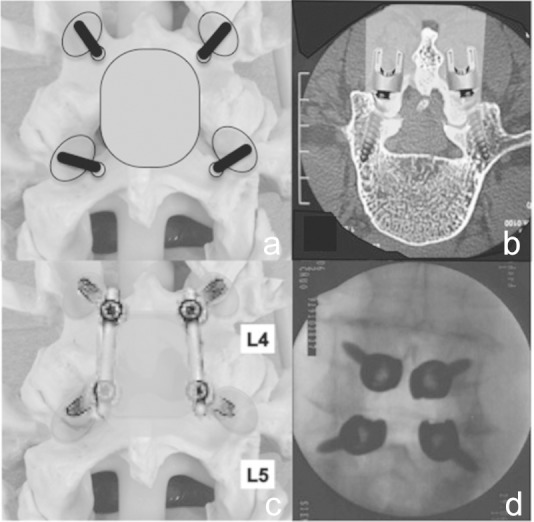
Fig. 4.

Surgical procedure of MIDLF part 2. a: Synthetic model showing laminectomy zone (gray oval area). b: Figure illustrated the minimum access route of MIDLF including microsurgical laminectomy and CBT screw fixation. c: Synthetic model showing accomplishment of the MIDLF with decompression and CBT fusion. d: Intraoperative AP image demonstrated the CBT screw insertion. CBT: cortical bone trajectory, MIDLF: midline lumbar fusion.
