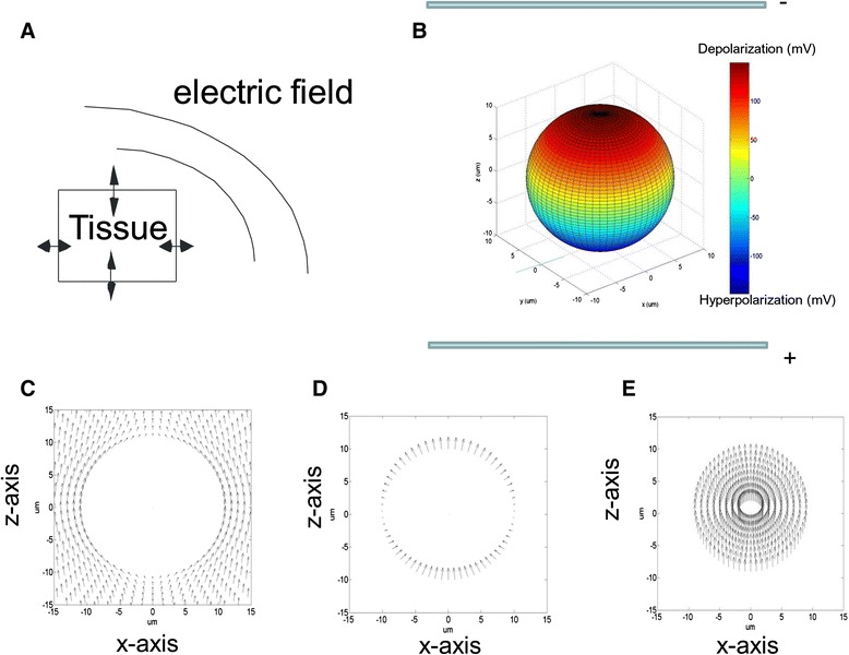
Fig. 1.

a. Conceptive illustration of the interaction between the biological tissue and the electric field which determines the overall polarization of the tissue. This interaction caused both cellular polarization and redistribution of the externally-applied field. b. Polarization pattern of a 3D model cell in a DC electric field generated by a pair of parallel-plate electrodes. The color bar indicates the amount of membrane potential change due to electric stimulation. All the parameters for this modeled cell is listed in [74]. c. Extracellular electric field distribution on the x-z plane (y = 0) (viewing the sphere from the y-axis). d. Electric field inside the membrane; e. Intracellular field distribution. Figures c to e are adapted from [74], with arrows to represent the direction of the electric fields. The size of the arrows represents the intensity of the electric field in each plots. For illustration purposes, size of the arrows are not in the same scale in c, d, and e. The maximal field intensity is 2531.6 V/m in c, 2.98 X 10⁷ V/m in d and 74.5 V/m in e, respectively
