Fig. 1.
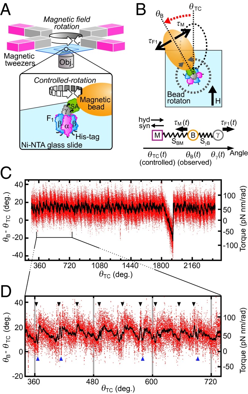
Oscillation of F1 torque probed using magnetic tweezers. (A) Experimental design (not to scale). Rotation of magnetic beads attached to F1 is manipulated with magnetic tweezers. (B) (Upper) Angular displacement of trapped beads in the presence of F1 torque. θTC indicates an angular position at which magnetic beads are trapped under a certain magnetic field in the absence of F1 torque (τF1). In the presence of τF1, the bead angle shifts to θB so that τF1 and magnetic torque (τM) are balanced. (Lower) Positional relationship between γ, bead, and magnetic trap center at time t during manipulation. SγB represents external elastic component that cause the shift of θB from θγ (for the definition and estimation see Methods, Torque Profile As a Function of θγ). SBM is the putative spring by magnetic trap. Its magnitude of torque is defined with Eq. 1. (C) Example trace of F1 torque as a function of θTC. Raw data points during controlled rotation (0.04 Hz, ATP hydrolysis direction) are shown in red. Black shows a result of 200-point median filtering. The substrate concentrations are 10 μM (ATP), 10 μM (ADP), and 100 μM (Pi) (condition i in Fig. 2C). (D) Magnified plot. Torque jumps are indicated by arrowheads.

