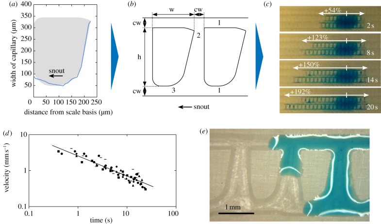
Figure 3.
Abstraction process of capillary structure for technical surfaces. (a) Exemplary capillary width along a single dorsal scale of P. cornutum (graph), based on analysis of histological slice series in figure 2c. That course of width was fit with a scale-like form (grey) to get a technically feasible scale surrounded by assumed channels of the capillary network. The minimal width was set to 50 µm. (b) Scale fits (from (a)) were arranged in arrays to design a structure for manufacturing (sketched in top view). To mimic the observed capillary network, longitudinal capillaries (1) were created that were interconnected (2). The course of capillary width (from (a)) is found below each subnatural fit (3). For manufacturing with use of a 0.3 mm cutter head the structure was constructed at 6 : 1 scale defined by scale fits with height h (1519 µm), width w (1086 µm) and a channel width cw (300 µm). (c) Sequence of a video analysis. The capillary structure was micro-milled into the surface of plain grinded epoxy resin at 6 : 1 scale for use of a 0.3 mm cutter head. They were analysed with 10 µl water droplets (stained with blue ink). (d) Measured velocities in the forward direction as a double logarithmic plot with fit according to the analytical model. Symbols indicate single measurements, n = 5. (e) Water flow on a microscopic scale. (Online version in colour.)

