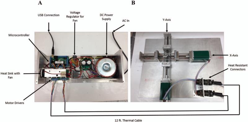
Figure 1.
Schematic of the automated thin film stretcher utilized in this study. (A) A USB linked microcontroller is linked to two stepper motor drivers which relay signals to two unipolar stepper motors through thermally protected wire. (B) The stepper motors are mounted to the axes. Each axis is composed of opposing direction lead screws to drive apart two aluminum mounts which grip and stretch the film.

