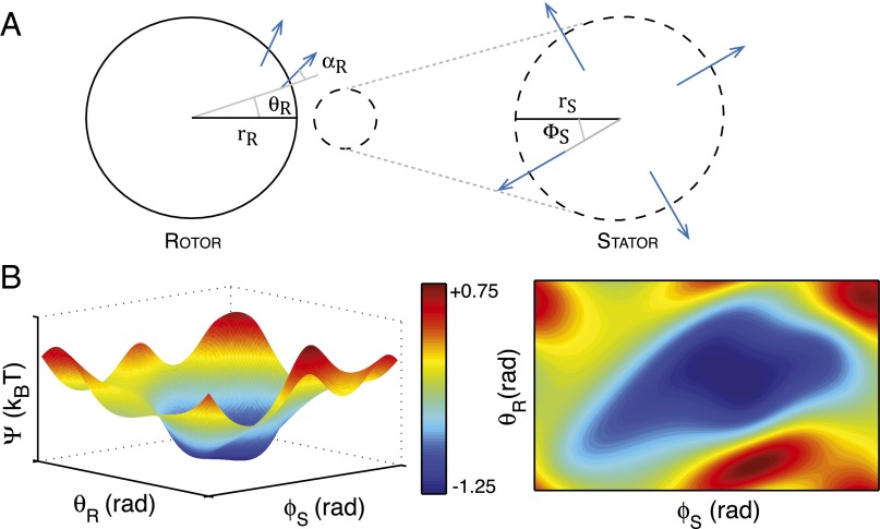
Fig. 2.
The predicted energy landscape during electrostatic steering. (A) Schematic of rotor and stator configurations; and are the angular coordinates of the stator and the rotor with respect to the horizontal; is the positive angle of the individual FliGs with respect to the radius. Blue arrows denote the direction of the dipole (10, 15). (B) Predicted surface and contour plots of the electrostatic energy vs. the stator and rotor angles. The predicted surface shows the existence of a wide and gently sloping energy well. Note that and are periodic variables with periods and , respectively; the above plots show one period of each. Our calculations consider a single stator centered at (21,−2,1) with the rotor centered at the origin (all distances in nanometers). Computations using this dipole approximation suggest a well of depth 1 kBT for this configuration (see SI Text for details).

