Fig. 5.

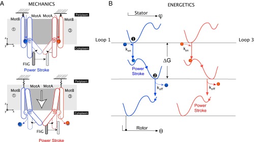
Dynamics of the rotor–stator interaction. (A) Mechanics of the power stroke. (Top) After the initial electrostatic steering, two protons bind to the charged Asp32 residues on the MotBs. The consequent rearrangement of hydrogen bonds induces an elastic strain in the straight MotA loops. Release of this strain results in synchronous kink and swivel motions about the proline hinge in both MotAs. As a result, a steric push is imposed on FliG, and the first half of the power stroke is performed by loop 1. Importantly, this motion also has a vertical component—the loops lower themselves out of the membrane. (Bottom) The lowering of the MotA loops exposes the protons in MotB to the cytoplasm, whereupon they are released. This results in a reset of the MotA loops, during which loop 3 carries out the second half of the power stroke. We note that this image depicts a 2D projection of a 3D motion: The motion of the stators is not constrained to the plane of the page. An observer sitting on the rotor axis sees the stator inchworm walking along the rotor using the FliGs as steppingstones. (B) Energetics of the power stroke. Because the two loops move in phase with each other, their energetic pictures are identical. We describe the free-energy landscapes using double-well Landau potentials. These landscapes are shown in blue for loop 1 and red for loop 3 with respect to the angles of the stator ϕ and rotor θ. We model the stator and rotor interaction using a steric force. This ensures that their motion and the values of the corresponding angles are very tightly tied to one another. The initial entrance of the proton into the ion channel () places the system within of the energy barrier. Thermal motions then result in the first half of the power stroke (Top and Middle). Exit of the protons into the cytoplasm () drives the reset, and the second half of the power stroke (Middle and Bottom).
