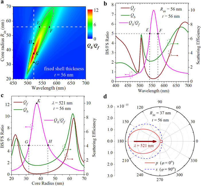
Figure 6. BS/FS ratio evolution of a core-shell nanoparticle with different core sizes.
(a) Contour plot of the BS/FS ratio as a function of the incident wavelength and the core radius. The shell thickness is fixed to t = 56 nm. Solid black line outlines the boundary at which the BS/FS ratio equals 5. Marked points E (Rin = 56 nm, λ = 541 nm) and B (Rin = 56 nm, λ = 574 nm) define a 33-nm-wide NZFS with BS/FS ratio higher than 5 in the horizontal dimension. Marked points G (Rin = 32 nm, λ = 521 nm) and D (Rin = 45 nm, λ = 521 nm) define a 13-nm-wide NZFS in the vertical dimension. Marked point K (Rin = 37 nm, λ = 521 nm) indicates that the BS/FS ratio reaches a value as high as ~12. (b) BS/FS ratio (magenta curve), BS efficiency (olive curve), and FS efficiency (wine curve) versus the incident wavelengths for a core-shell nanoparticle with a core radius of Rin = 56 nm and a shell thickness of t = 56 nm, corresponding to the special case indicated by a horizontal dashed line in (a). (c) BS/FS ratio (magenta curve), BS efficiency (olive curve), and FS efficiency (wine curve) versus the core radius are shown at the incident wavelength of λ = 521 nm, corresponding to the special case indicated by a vertical dashed line in (a). (d) 2D scattering patterns calculated for a core-shell nanoparticle with a core radius of Rin = 37 nm and a shell thickness of t = 56 nm at the wavelength of λ = 521 nm, corresponding to the marked point K in (a) and (c).

