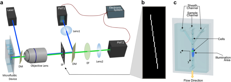
Figure 1. Implementation of imaging flow cytometer.

(a) Schematic diagram of the imaging flow cytometer system. DM, dichroic mirror; SF, spatial filter; EF, emission filter; PMT, photomultiplier tube. (b) Spatial filter design that has ten 100 um by 1 mm slits positioned apart in the way of one is immediately after another in both x-direction and y-direction [labeled in (c)]. (c) Microfluidic device in which suspended cells are controlled by sheath flow to travel in the center of the microfluidic channel at a uniform velocity.
