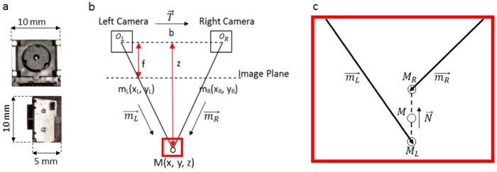
Fig. 3.

Bionocular stereo vision setup. (a) CMOS area sensor. (b) Stereo vision triangulation with two cameras with optical centers, OL,R; baseline, b; focal length, f; and imaging distance, z. mL.R are projections of M at the camera image plane. c) Stereo vision noise may result in non-coplaner calculated three-dimensional rays. Here, the midpoint between MR and ML is used to approximate the three-dimensional intersect, M.
